Sensitivity Analysis of the IQM System Using Monte Carlo Simulation
Test purpose
Evaluation of the IQM sensitivity to errors in segments using EGSnrc/BEAMnrc Monte Carlo (MC) codes.
Test method
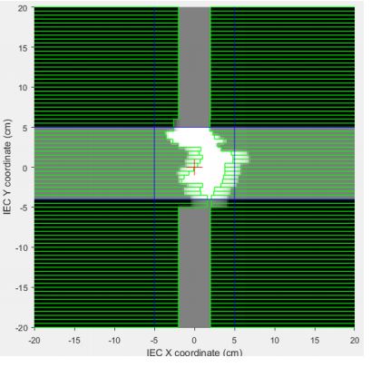
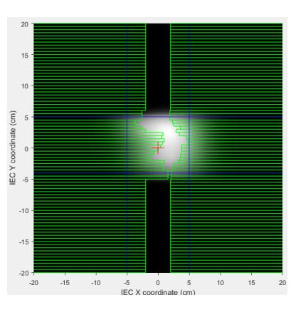
Sensitivity analysis (SA) techniques were applied to study the significance of small alterations of the field (segment) sizes on the IQM signal response. One hundred and eighty multi leaf segments were analyzed with methods that included scatter plots (SP), brute force, variance-based (VAR), and standard regression coefficient SA.
The segments were altered randomly within ±1, ±2, and ±3 mm leaf steps for 10 MV photon beams.
Test results
In total, 6 original segments were each altered 30 times randomly with ±1, ±2, and ±3 mm positional errors. For each segment, a Monte Carlo simulation was done to determine the IQM signal. Sensitivity analysis results indicated that the IQM is sensitive to detect these alterations in SA. The sensitivity is more pronounced in small SA.
Conclusion
The sensitivity of the IQM in this study shows its potential to detect small alterations in SA. The SP and VAR relation to SA is approximately constant at large SA but displays power function relationships at smaller SA values. All sensitivity analysis methods employed in this study indicated that the IQM signal (?) will indicate small segments alterations even for the larger segments.

The physics behind the IQM Signal
Scope
Outline the calculation model for IQM in terms of the physical characteristics and behavior of linear accelerators.
Expected inputs for signal prediction
- Chamber characterization
- Treatment unit (Linac) characterization
- Collimation attenuation
- Fluence profiles
- Patient treatment description
- Both static field-in-field and dynamic delivery modes
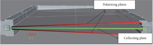
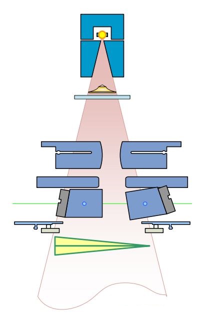
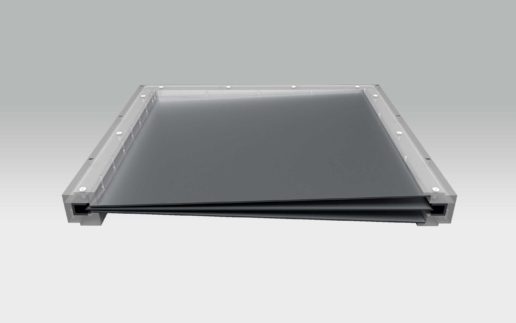
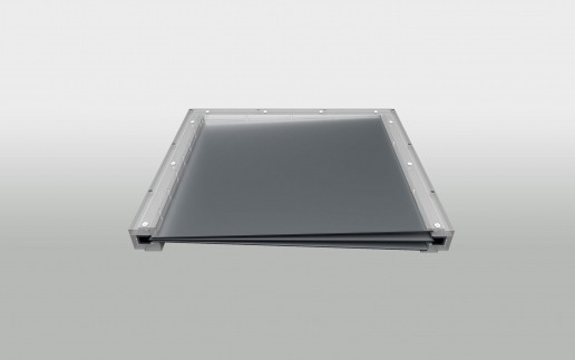
IQM chamber properties
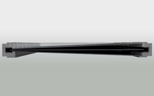
- Sloped electrode chamber
- Spatial gradient = delivery position encoding
- Characterized by
- Reference field normalization
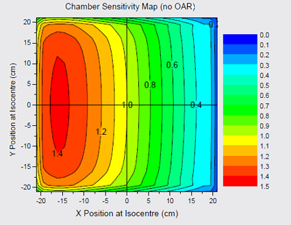
- Gradient (sensitivity) map
- CSM, (????)
Linac characterization
- Behaviour to capture
- Output change with field size
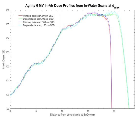
- Radial Profile
- Transmission through collimating elements
- Source Assumption
- Primary point source
- Extended secondary source
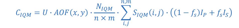
Fundamentals of signal calculation
- ? = MU setting for segment
- ??? = output change with field size (residual…)
- ???? / ?×?= normalization (electrometer reading)
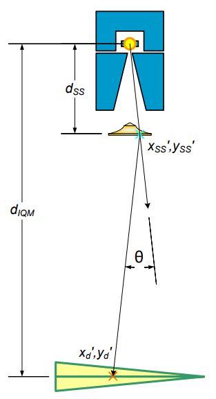
- ?p, ?s = primary and secondary source intensity matrix
- ?? = fractional contribution from secondary source
- ???? = chamber positional sensitivity matrix
Primary source intensity
- Starts with open source profile
- Assume radially symmetric intensity profile
- Apply effect of collimation attenuation
- Works on an area weighted average rather than an intensity to a point
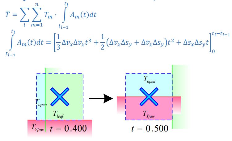
Primary Source Modulation
- Area-Weighted Transmission through collimating elements subdivided in regions of transmission and time for each pixel
Secondary source
- Extended source geometry
- Positioned at bottom of flattening filter
Secondary source modulation
- More complex geometry
- Non-divergence matched
- Multiple off-axis sources
- Complex element shape shading
- Simplify calculation
- Static “snapshot” calculation
- Sampling point geometry
- Layered collimating element

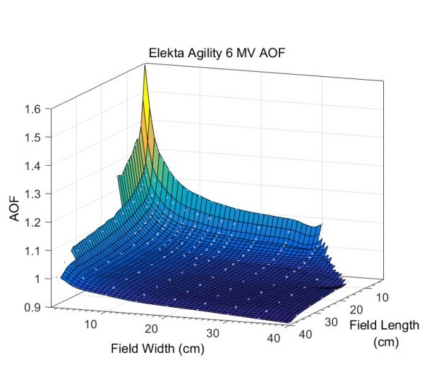
Area output factor characterization
- Captures changes in output due to field size effects
- Derived from a series of rectangular field measurements
- Behaves as a “residual”
- Some effects accounted for byextended source
- Rederived for tweaks in source description & transmission
- Look-up according to average field width, length

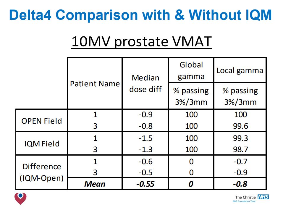
Integrating the IQM into Philips Pinnacle 9.8
Step 1: Comparison of measured data
Comparison of data measured with & without IQM in plotting tank (6, 10 & 6FFF).
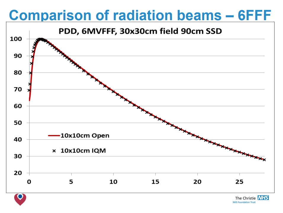
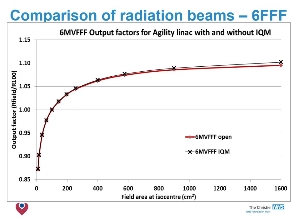
Conclusion
- No significant differences in O/P factors was detected.
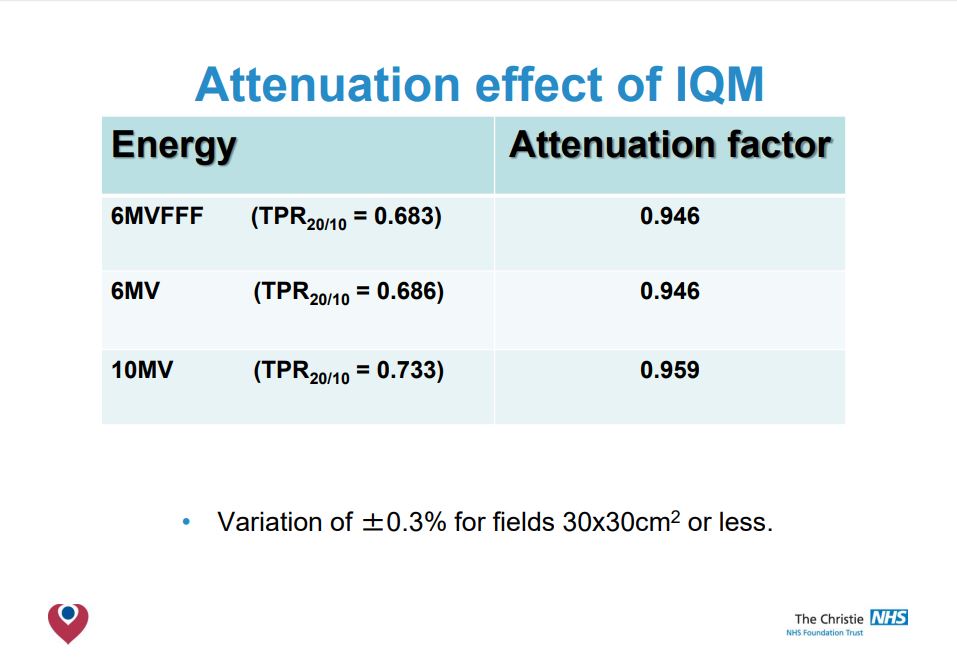
- The beam attenuation is found to be a fixed amount for each energy.
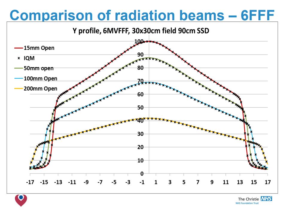
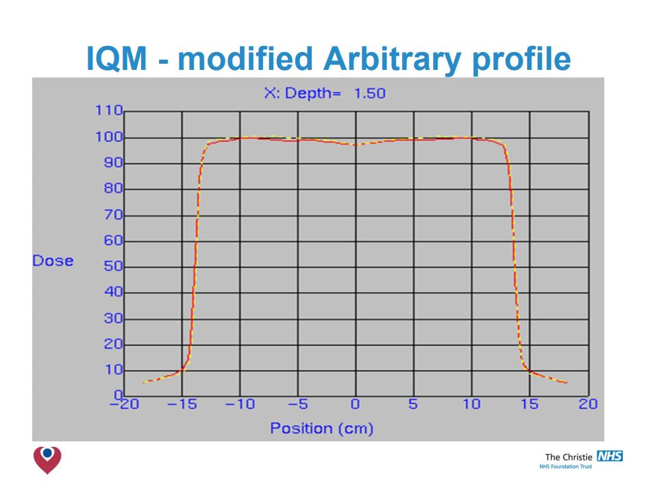
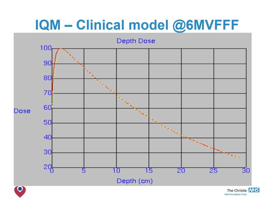
- IQM has little effect on PDD beyond Dmax or on profiles <20x20cm.
- For 6 & 10 MV modelling at larger radial distances needed review.
Step2: Comparison with existing clinical models
Step3: Initial validation
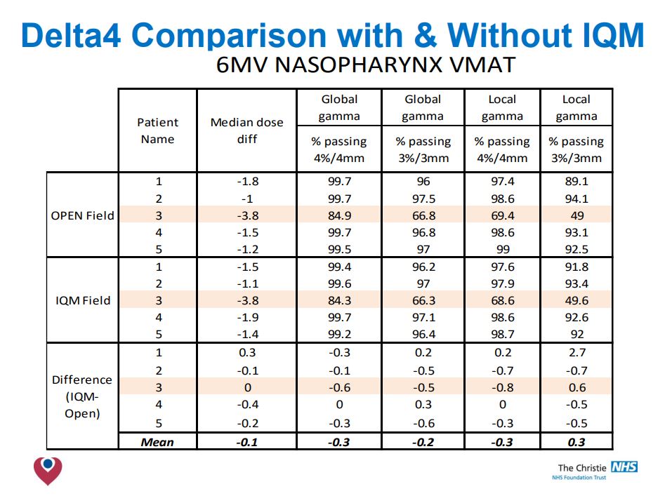
Conclusions
- The build up region is modified by the presence of the IQM, reducing ‘skin sparing’.
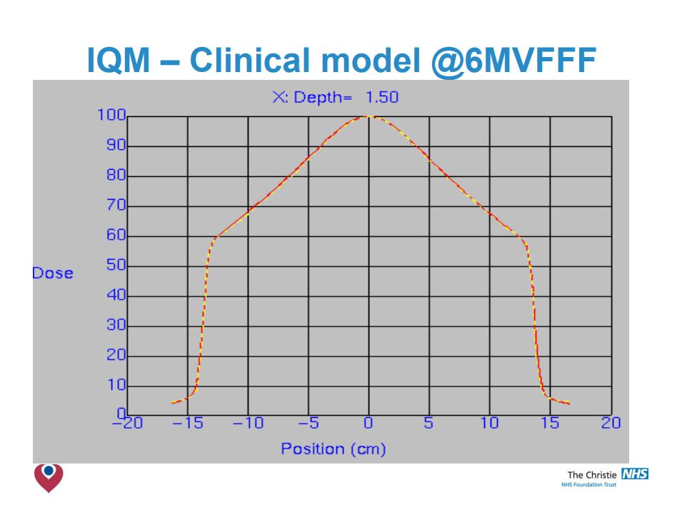
- Smaller field PDDs & Profiles are not affected by IQM.
- Larger fields have shoulders drop, more notably at shallower depths.
- Adjustment of arbitrary fluence profile improved agreement – but not observable clinical benefit.
- Clinical models acceptable at 6MV & 10MV.
- Simple correction factor to change MUs was all that was required in Pinnacle 9.8.
- Validation of your clinical models necessary when integrating the IQM into your planning system, but modifications are likely to be small.
The Transmission Factor
of the IQM Detector
Test purpose
The influence of the IQM transmission detector on photon beam properties was evaluated in a pre-clinical phase, using data from nine participating centers. The beam attenuation due to IQM was measured and the dependence of the transmission factors on beam energy and field size was investigated.
Test method
The transmission factor was calculated by means of measured absorbed dose at 10 cm depth for all available energies and field sizes.
Test results
The mean transmission factors of the IQM detector showed statistically significant energy dependence for all investigated flattened and FFF beams. It ranged from 0.9412 to 0.9589 for standard beams 6 MV to 18 MV, while for 6 MV FFF and 10 MV FFF beams it was 0.9440 and 0.9533, respectively. While it might be argued that transmission factors close to 1 are preferable, the authors emphasize that every transmission factor has to be adequately incorporated into the TPS. On the other hand, variations in the range of 2% or more of the transmission factors versus field size can be considered as a shortcoming for the straightforward use within TPS. In that case no single value can be recommended and a new beam model needs to be introduced to the TPS. The maximal dispersion of the aggregated measurements from all participating centres and for all
field sizes from 1 cm × 1 cm to 20 cm × 20 cm was less than 0.49%, with a maximal cumulative uncertainty of 0.58%.
Conclusion
The transmission factors calculated for the attenuation due to the presence of IQM show energy dependence but only weak dependence on field size, with the maximum dispersion of measurements to be < 0.5% across 9 treatment machines, 6 energies and 9 field sizes.
The mean transmission factors of the IQM detector can be used either as tray factors within TPS for the particular linear accelerator energies or alternatively as modified outputs for the respective beam energies.
Influence of the IQM Detector on the surface dose
Test purpose
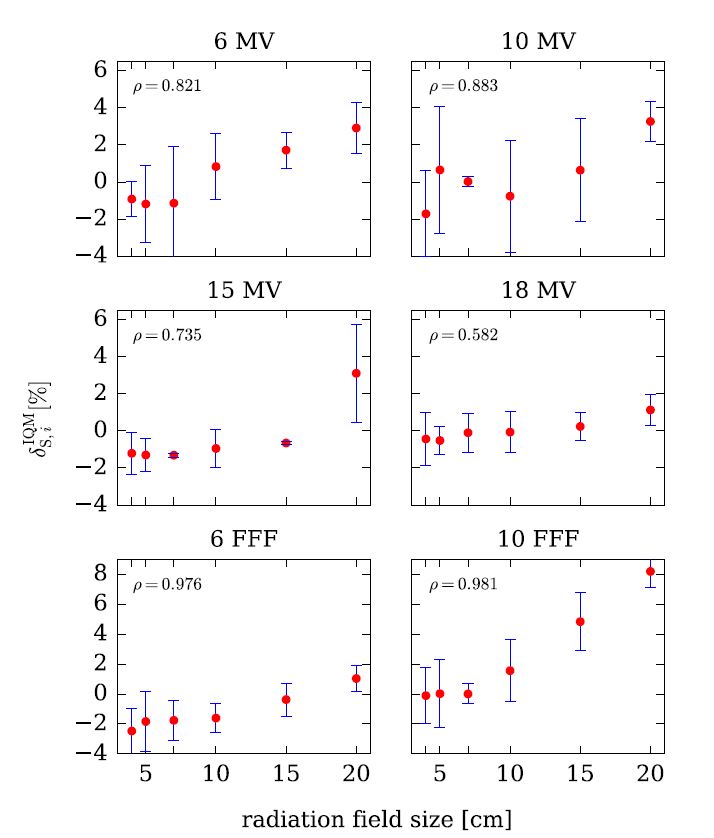
The influence of the Integral Quality Monitor (IQM) transmission detector on the surface dose was evaluated using data from nine participating centers.
Test method
The change in surface dose with/without IQM was assessed for all available energies (4 standard, 2 FFF) and field sizes from 4 cm × 4 cm to 20 cm × 20 cm.
Test results
Pearson’s product–moment correlation coefficient ρ indicates a positive linear correlation between surface dose and the radiation field size for all studied flattened and unflattened beams, however, except for the 20 cm x 20 cm field size for the 10 MV FFF beam, the change in surface dose did not exceed 3.3%.
Conclusion
This study demonstrates clinically negligible changes in the surface dose for all investigated beams. A modest increase of surface dose when IQM is in the beam path can be considered acceptable and not a limiting factor for its clinical use.
Therefore, the time needed to implement the IQM system can be shortened since no additional commissioning beyond taking the beam attenuation into account (as a transmission factor or modified output factor) is needed regarding beam properties such as beam hardening and surface dose.
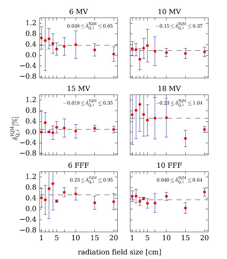
Influence of the IQM Detector on the beam quality
Test purpose
The influence of the Integral Quality Monitor (IQM) transmission detector on the beam quality (beam hardening) was evaluated using data from nine
participating centres.
Test method
For 6 different nominal photon energies (4 standard, 2 FFF) and square field sizes from 1 cm × 1 cm to 20 cm × 20 cm, the effect of IQM on beam quality was assessed from the PDD20,10 values obtained from the percentage dose depth (PDD) curves, measured with and without IQM in the beam path.
Test results
The presence of IQM caused a small but measurable and statistically significant beam hardening effect. Beam hardening was most pronounced for the 6 MV FFF beam where it increased to 0.53%. Statistical significance of the beam hardening effect was demonstrated (p < 0.01) for all investigated beams except for 15 MV where no statistically
significant difference was found.
Conclusion
As beam quality changes were always lower than 0.53%, our conclusion is that this effect has no considerable clinical relevance.
This study demonstrates clinically negligible changes in beam quality for all investigated beams. Therefore, the time needed to implement the IQM system can be shortened since no additional commissioning is
needed regarding this beam property.
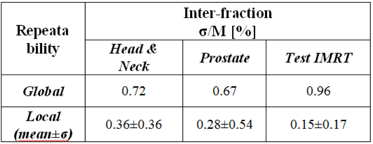
Inter-fractional signal constancy
Test purpose
Test the inter-fractional (long-term) repeatability of the IQM signal.
Test method
Inter-fraction repeatability was checked by delivering three IMRT treatments for more than seventy times in a period of thirty days. The chosen treatments were: a head & neck (H&N), a prostate and a test IMRT treatment. For each segment of the IMRT treatment sigma and M were evaluated over the number of repetitions (21 for H&N; 30 for prostate and „Test“ IMRT). In H&N and prostate tests gantry rotation and small fields of different shape and size were considered.
Test results
Global and local inter-fraction detector repeatability results demonstrate the optimal detector performance for highly complex IMRT treatment techniques.
Conclusion
IQM provides a high long-term signal reproducibility for complex IMRT plans.
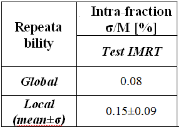
Intra-fractional signal constancy
Test purpose
Test the intra-fractional (short-term) repeatability of the IQM Signal.
Test method
Intra-fraction repeatability was checked by delivering 15 times (about 2 hours) the same plan, composed by 17 square fields 4 cm x 4 cm and 1 larger field 10 cm x 10 cm irradiating different regions of the detector.
Test results
Global and local intra-fraction detector constancy results demonstrate the optimal detector performance for IMRT plan QA.
Conclusion
IQM provides a very good short-term signal reproducibility for complex IMRT plans.
Picket Fence Test with IQM
Test purpose
Investigation of the error sensitivity of the IQM signal.
Test method
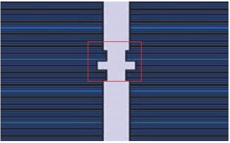
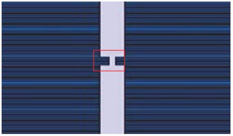
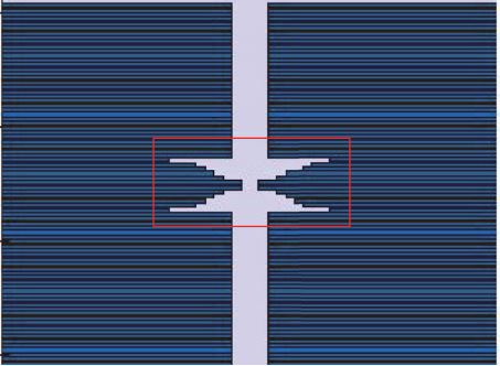
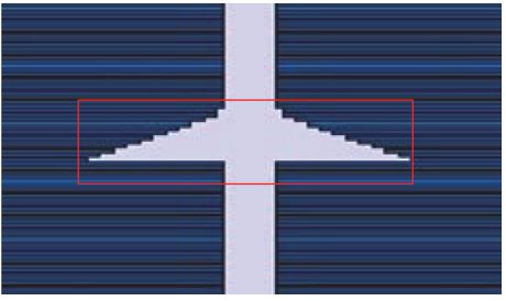
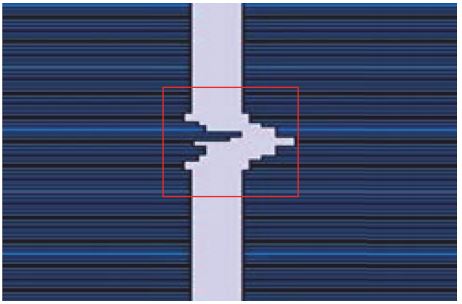
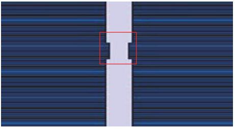
Picket Fence type fields were used to evaluate the sensitivity of the IQM Detector for MLC leaf errors.
A single leaf offset was intentionally introduced during delivery of various Picket Fence fields with segment apertures of 3×1, 5×1, 10×1, and 24x1cm2 .
Both 2mm and 5mm decrease in a single MLC leaf width were used.
Test results
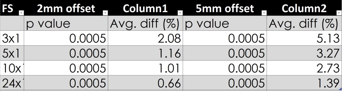
- Statistical analysis indicates that the dosimetric differences detected by IQM were significant (p < 0.05) in all Picket Fence test deliveries.
- The largest average IQM signal response of a 2 mm leaf error was found to be 2.1% and 5.1% by a 5mm leaf error for 3×1 cm2 field size.
- The same error in 24×1 cm2 generates a 0.7% and 1.4% difference in the signal. See above table for detail.
These results were achieved completely automatically by the IQM system simply delivering a treatment plan designed as a picket fence test.
Conclusion
Small MLC leaf error can be detected. The sensitivity is more pronounced for smaller field sizes.
IQM could be beneficial for the verification of stereotactic treatments.
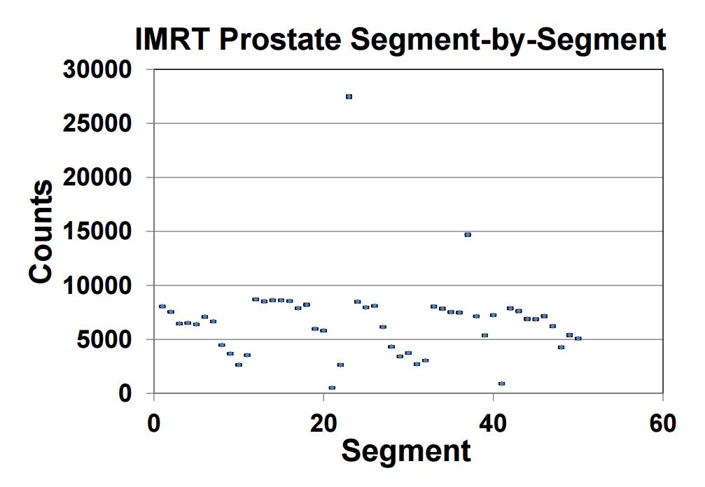
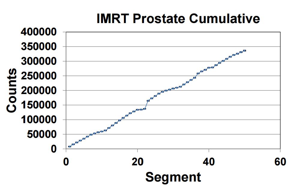
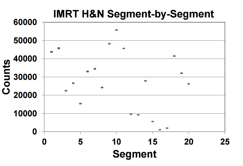
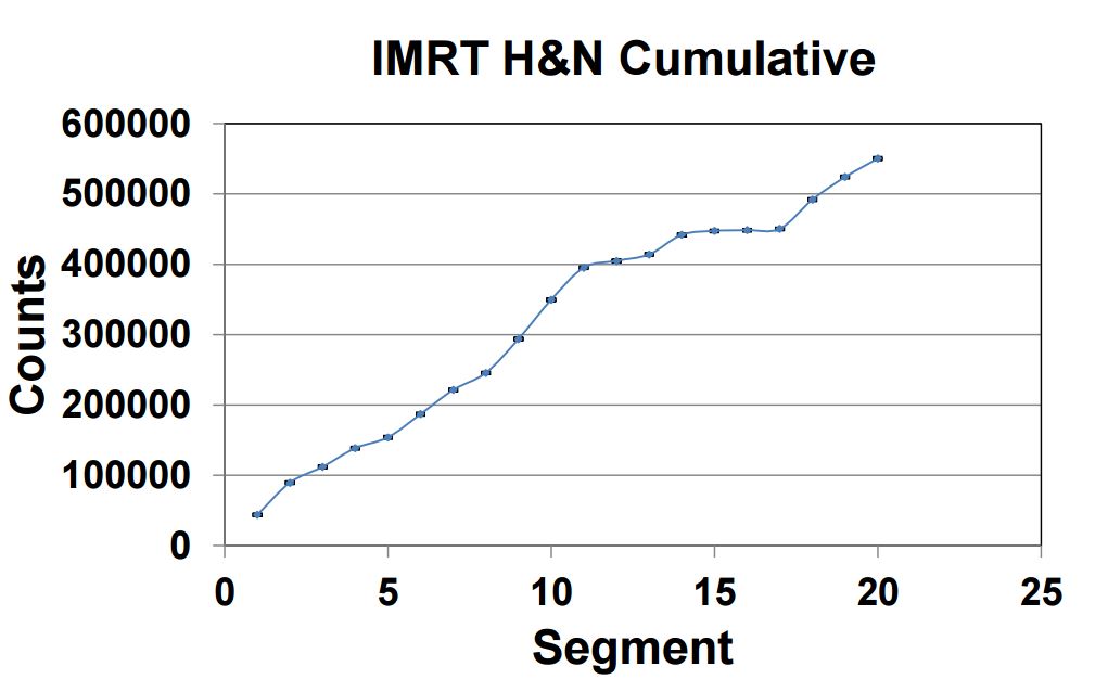
Signal constancy for clinical IMRT and VMAT plans
Test purpose
Investigation of the constancy of IQM signal for conventional intensity modulated radiation therapy (IMRT) and rotational volumetric modulated arc therapy (VMAT)
Test method
The stationary and rotational dosimetric constancy of IQM was evaluated, using five field IMRT and single- and double-arc VMAT plans for prostate and head-and-neck (H&N) patients.
The plans were repeated three times for each measurement over several days to assess the constancy of IQM response.
Test results
Repeated IQM measurements of prostate and H&N IMRT deliveries showed 0.4 and 0.5% average standard deviation (SD) for segment-by-segment comparison and 0.1 and 0.2% for cumulative comparison. The corresponding SDs of the cumulative signal for VMAT deliveries were 0.7, 1.3%, respectively.
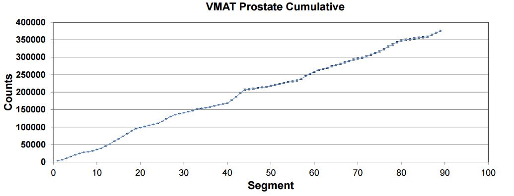
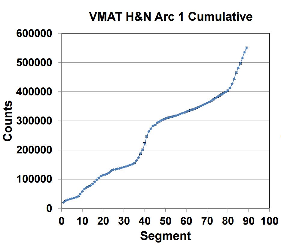
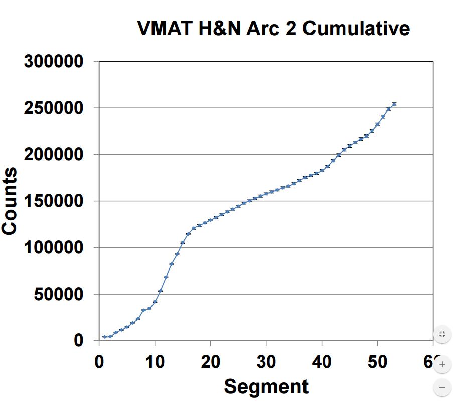
Conclusion
IQM provides an effective means for realtime dosimetric verification of IMRT/VMAT treatment delivery.